
| MAS ETH ARCH/CAAD - 2006/07 | Student Pages
Master of Advanced Studies in Architecture, Specialization in Computer Aided Architectural Design | 065-0005/6
Supervision: Prof. Dr. Ludger Hovestadt, Philipp Schaerer
Chair of CAAD, ETH Zurich
Module 02 : Parametric Facades in Digital Project / Catia (Supervised by Steffen Lemmerzahl)
Prologue
This module is an experimental course to design parameter-driven facades that are adapt to the local conditions. Each building element is drafted in the parametric modeller and controlled by various kinds of parameters like sun position, noise emission, concept or programs of the building and so on.
Design motif
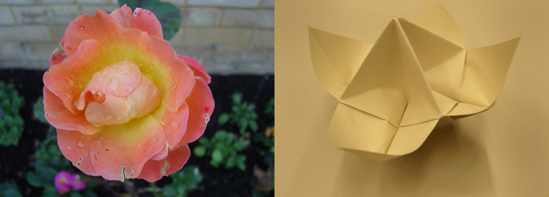
Flowers blossoms affected by environment i.e. sun, soil, water etc.. While passing by a street in London, I find a nice looking flowers. I am fascinated by the color and shape of their petals, I think it is a good idea to adjust the feature of flowers to the designing of facade. To do so, I abstract the actual flower into simple paper model and then think about which components of petaline model can be available.
Parametric design
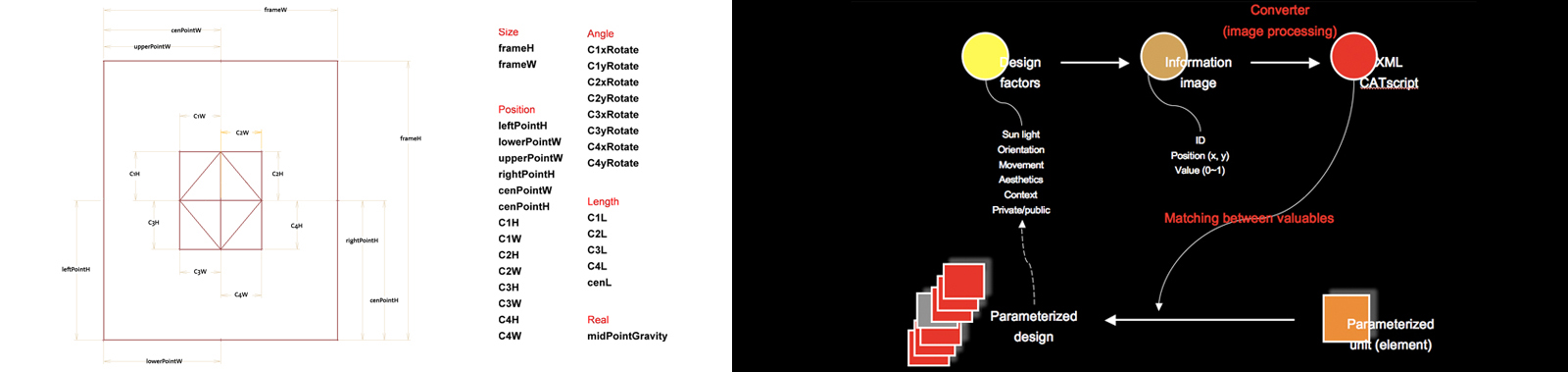
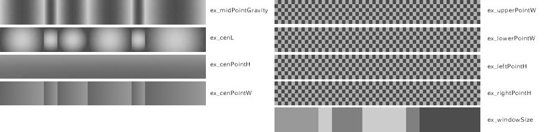
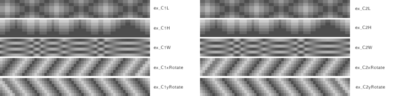
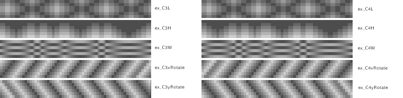
At the same time, I think of how to parameterize elements of flower model and how to assign values into each element. So design factors i.e. 'Sun light', 'Orientation', 'Movement', 'Context', 'Aesthetics (designer's intention)', 'Private / Public' and the like are expressed as bitmap images. Actually bitmap image is composed of pixels which have a position value and color value (0 ~ 1). In this case, facade of this building is comprised with 366 modules and one bitmap image represent one parameterized element of modules.
Parameterization
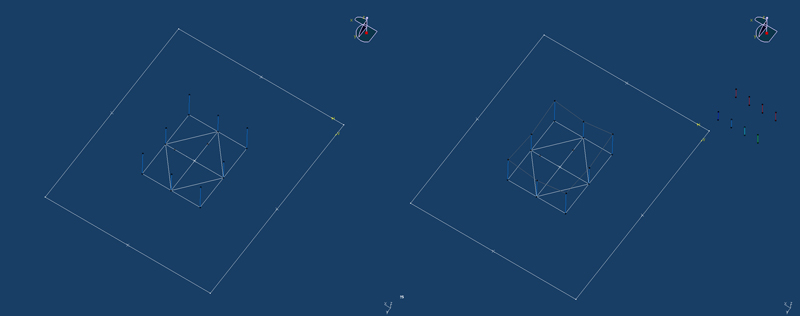
One module is like this. The schematic shape of one basic module is sketched. First, 1 center point is located within the boundary of the module and 4 points (C1, C2, C3, C4) are specified around the center point. 4 points are linked and other 4 points are also located on the midpoints of each line that are drawn just before and also linked. Additionally 2 lines are added to make innermost shape.
There are 4 outermost vertices between the boundary lines and move along these lines. Based on this elementary sketch, I try to give more dynamic movement to this facade similar to the behavior of flowers. So I set 9 vertical lines and make these lines varied according to angle and length.
Modeling
Skeleton
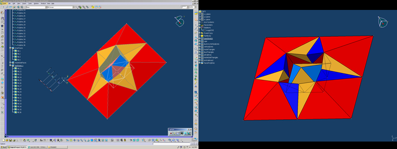
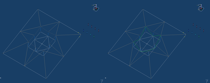
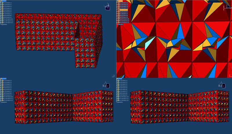
To easily convert the angles of each vertical lines, I make 4 dummy reference lines. If the angle of each dummy line is modified. the angle of one original vertical line is concurrently changed. Also the angles of the 2 neighboring mid-vertical lines are calculated and altered. The skeleton of the basic module is like pic. To get a producible facade, each face is drawn by triangle and based on final skeleton, real volumetric model is created.
BMP for Parameter values
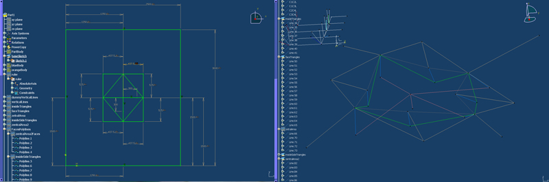
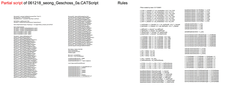
In this case, 29 parameters are used. each parameter change length, angle, and real value and is related to design factors. 1 floor has 61 modules and this building is 6 storey building. So 1 BMP image must represent 366 values. In case of a BMP image that is colored using gradation, the average value of each pixel is measured. Lastly all BMPs are changed into CATScript (CATIA Script).
Rules
Result - Perspectives, Plans, Elevations
Perspectives
 Plans - top & bottom
 Elevation 1 & 2
 Elevation 3 & 4
 Detailed face
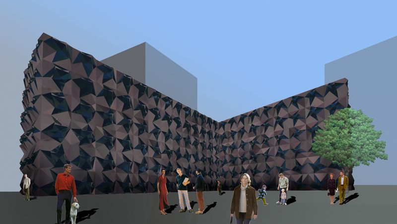
 Final perspective
* unfolded: Unfolded facade
Main | Module01 | Module02 | Module03 | Module04 | Module05 | Module06 | Module07
-- LeeSeongKi - 02 Nov 2006
|
This website has been archived and is no longer maintained. |
